


|
|

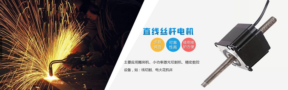
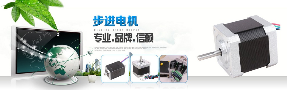
 Hybrid Stepper Motor
|
Name: Kevin Chen |


How to Select a Stepper Motor |
| Author : Snowit Motor |
There are several important criteria involved in selecting the proper stepper motor:
1. Desired Mechanical Motion
2. Speed Required 3. Load 4. Stepper Mode 5. Winding Configuration With appropriate logic pulses, stepper motors can be bi-directional, synchronous, provide rapid acceleration, run/stop, and can interface easily with other digital mechanisms. Characterized as having low-rotor moment of inertia, no drift, and a noncumulative positioning error, a stepper motor is a cost-effective solution for many motion control applications. Generally, stepper motors are operated without feedback in an open-loop fashion and sometimes match the performance of more expensive DC Servo Systems. As mentioned earlier, the only inaccuracy associated with a stepper motor is a noncumulative positioning error which is measured in % of step angle. Typically, stepper motors are manufactured within a 3-5% step accuracy. Motion requirements, load characteristics, coupling techniques, and electrical requirements need to be understood before the system designer can select the best stepper motor/driver/controller combination for a specific application. While not a difficult task, several key factors need to be considered when determining an optimal stepper motor solution. The system designer should adjust the characteristics of the elements under his/her control, to meet the application requirements. Anaheim Automation offers many options in its broad line of stepper motor products, allowing for the maximum amount of design flexibility. Although it may appear overwhelming to choose, the result of having a large number of options is a high-performance system that is cost-effective. Elements needed to be considered include the stepper motor, driver, and power supply selections, as well as the mechanical transmission, such as gearing or load weight reduction through the use of alternative materials. Some of these relationships and system parameters are described in this guide.
Inertial Loads
Inertia is a measure of an object’s resistance to a change in velocity. The larger an object’s inertia, the greater the torque is required to accelerate or decelerate it. Inertia is a function of an object’s mass and shape. A system designer may wish to select an alternative shape or low-density material for optimal performance. If a limited amount of torque is available in a selected system, then the acceleration and deceleration times must increase. For most efficient stepper motor systems, the coupling ratio (gear ratio) should be selected so the reflected inertia of the load is equal to, or greater than, the rotor inertia of the stepper motor. It is recommended that this ratio not be less than 10 times the rotor inertia. The system design may require the inertia to be added or subtracted by selecting different materials or shapes of the loads. NOTE: The reflected inertia is reduced by a square of the gear ratio, and the speed is increased by a multiple of the gear ratio.
Frictional Loads
All mechanical systems exhibit some frictional force. The designer of a stepper motor system must be able to predict elements causing friction within the system. These elements may be in the form of bearing drag, sliding friction, system wear, or the viscosity of an oil filled gear box (temperature dependent). A stepper motor must be selected that can overcome any system friction and still provide the necessary torque to accelerate the inertial load. NOTE: Some friction is desired, since it can reduce settling time and improve performance.
Positioning Resolution
The positioning resolution required by the application may have an effect on the type of transmission used, and/or selection of the stepper motor driver. For example: A lead screw with 5 threads per inch on a full-step drive provides 0.001 inch/step; half-step provides 0.0005 inch/step; a microstep resolution of 25,400 steps/rev provides 0.0000015 inch/step. Stepper Motor Modes Stepper motors are driven by waveforms which approximate to sinusoidal waveforms. There are three excitation modes commonly used with stepper motors: full-step, half-step and microstepping. |